Maya 2020 fundamentals - modelling the real world
Get halfway through a model and find it's an unworkable mess? Can't add edge loops where you need them? Can't subdivide a mesh properly? If any of this sounds familiar check this course out.
# 1 19-11-2009 , 10:32 AM
ctbram's Avatar
Moderator
Join Date: Jan 2004
Location: Michigan, USA
Posts: 2,998

maya version of modo piston

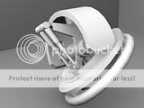
I just watched the modo 401 hard surface subd modelign techniques video. I was really impressed with the parts that Andrew Brown created in the video and I thought I would take a stab at recreating them in maya.

Here is the piston assembly. It was easier then I thought it would be. Watching the video it seemed that without the modo the "background object constraint" option intersecting the two upper cylinders would be hard in maya but it was actually quite simple.

I just did a boolean:union of the two cylinders and snap/merged a couple vertices, added a 2 segment bevel and viola. Make sure the intersecting parts have the same number of edges in the intersecting area. You just have to be intelligent about the number of sides you pick in each of the cylinders to minimize distortion.

The valve object is just a 6 sided poly cylinder with a number of extrusions, bevels to tighten edges, deleted a couple edges and redrew the edge flow with split polygon and finally used the crease polygon edge tool to tighten the edges of the area closest to the piston (I never used this tool before but I will be using it a lot in the future).

user added image
user added image
user added image
user added image
user added image


"If I have seen further it is by standing on the shoulders of giants." Sir Isaac Newton, 1675

Last edited by ctbram; 19-11-2009 at 11:24 PM.
# 2 19-11-2009 , 11:53 AM
ColdWave's Avatar
Registered User
Join Date: Sep 2006
Location: Bulgaria, Vidin
Posts: 1,310
It's about the skills not the program i think... user added image

A man with paint can do things like man with Photoshop ... depends on the skills user added image

# 3 20-11-2009 , 01:20 PM
ctbram's Avatar
Moderator
Join Date: Jan 2004
Location: Michigan, USA
Posts: 2,998
Perfecto sent me an email asking for a wire frame of the unsmoothed T connection of the piston / actuator.

This is the message:

Your piston looks really nice and smooth where the parts are interconnected. Can you email me a screen shot of the low rez wire frame before smoothed? It would allow me to compare with how I do it because it's always a trouble area for me. I can make it smooth like yours but it takes some doing for me.

Here you are Perfecto. I sent a reply to your mail describing the process. Let me know if you are confused and I can post a build sequence to show how I connected and controlled the edges.

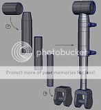
This shows the edge flow for the union of the two 12-sided poly cylinders of the main body and the union of the 6-sided cylinder for the hydraulic connection on the side.

The process it always the same (I do these 4 steps, IN THIS ORDER):

1. boolean union the two parts
2. clean up the edges (if you choose the location and number of sections of the two parts wisely the cleanup is easy, if you choose poorly then the cleanup can be very hard).
3. add edges to control the smoothed edge flow. Note the two edges above and below the hydraulic fluid connector on the side - If these were not there - especially the bottom two - the fillet between the intersection of the two parts would be non-uniform.
4. add bevels (or edges) to tighten up areas. (I try to make saves BEFORE or AFTER I do bevels because it's hard to manually undo them after you delete the history. If you just add edge loops they can simply be deleted. If you want to go back to a previous state the backup can save you a lot of grief. Look at the bevel where the hydraulic connector intersection is, because it's a 1 section bevel the original intersection loop of the two parts is gone, so you would have to delete all the faces and manually have to try to recreate the intersection loop this can be a real pain and cause your surface planes to start going all wonky).

note: I tend to prefer 2 segment bevels to tighten edges because its a single operation and I have more precise control of the offset vs. eyeballing the insertion of edge loops. I just wish I did not have to constantly delete the history in maya which forces me to make a zillion backups - which becomes a logistical nightmare. You do have to chose between the two options carefully as bevels can cause surface planes to go wonky.

Cheers.

user added image


"If I have seen further it is by standing on the shoulders of giants." Sir Isaac Newton, 1675

Last edited by ctbram; 20-11-2009 at 02:19 PM.
# 4 20-11-2009 , 02:10 PM
daverave's Avatar
The thin red line
Join Date: Aug 2009
Location: England
Posts: 4,472
just a question, why boolean the parts together could you not merge vetices together one by one or is this slower?

# 5 20-11-2009 , 02:56 PM
ctbram's Avatar
Moderator
Join Date: Jan 2004
Location: Michigan, USA
Posts: 2,998

Originally posted by daverave
just a question, why boolean the parts together could you not merge vetices together one by one or is this slower?

The boolean operation gives you a more precise edge loop between where the two parts intersect then you can draw by eye. Look at the intersection of the two parts - some of the edges intersect in the middle of a face so there is no vert to simply merge a vert too.

Without the boolean operation you would have to use the split edge loop tool (with the split at edges only option turned off) to cut the edge loop where the two parts intersect , then delete the faces, then manually snap vertices. I use this option in cases where booleans cause problems, which works but is a slower workflow in most cases; however, I find I rarely have too because I understand how booleans work.

Booleans are useful and powerful. You just have to be smart about using them. Booleans get a bad rap because people don't really understand how to use them properly then go off ranting about them.

If the geometry is accommodating then boolean + cleanup + vert snap is a faster and more accurate work flow. However, there are cases where the other method is necessary because of the topology.


"If I have seen further it is by standing on the shoulders of giants." Sir Isaac Newton, 1675

Last edited by ctbram; 23-11-2009 at 02:54 PM.
# 6 20-11-2009 , 04:07 PM
honestdom's Avatar
The Nurb Herd
Join Date: Oct 2007
Location: London
Posts: 2,381
i'm not sure i get it... this must have taken about ten minutes. Is it part of something larger? I've seen you model some more complex things.

I was also wondering why you appear to be fascinated with hard surface modeling? If you can do organic modeling you can do hard surface stuff, I mean its got less rules, its not deforming, you can make it look more detailed with simple primitives.
The head of 3D modeling here even said to some of us that he looks at peoples organic modeling and finds that most of the time if they are good at that, then they will be good at hard surface stuff.

...i'm just curious is all. user added image

# 7 20-11-2009 , 06:21 PM
ctbram's Avatar
Moderator
Join Date: Jan 2004
Location: Michigan, USA
Posts: 2,998
It's not the complexity of the part, it's the process that I am exploring.

I wanted to compare how I would create a part in maya as apposed to the way Andrew did it in modo. He created a ring of faces around the vertical piece, separated it, then used one of the coolest features in modo (the background constraint object) to just push it against the horizontal piece. At the time I thought it allowed more control than maya but after building it I feel I can achieve as good a result using booleans in maya (and faster too).

Creating complex compound shapes with highly controlled edges is what I find challenging about hard surface modeling. I think hard surface modeling is much more challenging then organic, especially with tools like zbrush now for digital sculptors.

I like both inorganic (hard surface) and organic modeling though.

But anyway this is more a diversion, I am more interested in learning to texture lately and I just needed to take a short break. I watched the modo video and I liked the approach Andrew took with the way he constructed some of the parts in the demo. I just wanted to recreate some of them in maya.

Then I started thinking this kind of stuff might help someone just learing maya. I would have loved to have seen stuff like this when I was just learning.

The piston was just the first one. I am going to recreate the entire foot section so there will be more coming. In fact, I have a itch to model the entire mech in maya.

Oh it it actually took about 5 minutes to make (lol). Sure you could just stuff two components into one another and combine them and 90% of the time you'd never notice.


"If I have seen further it is by standing on the shoulders of giants." Sir Isaac Newton, 1675

Last edited by ctbram; 23-11-2009 at 02:56 PM.
# 8 20-11-2009 , 07:12 PM
daverave's Avatar
The thin red line
Join Date: Aug 2009
Location: England
Posts: 4,472
please carry on, if I learn just one thing from a posting I think this is what sites like this are all about...........dave

# 9 20-11-2009 , 07:23 PM
Perfecto's Avatar
Registered User
Join Date: Mar 2007
Location: TN (USA)
Posts: 1,889
Thanks a whole heap ctbram. You method is what I use for organic modeling but never even considered it for hard surface modeling. I usually use split edge loop tool, then extrude..but always have to go back and adjust the side vertices to get rid of artifacts which is what I don't like having to do. I look forward to using the Boolean option instead. I too LOVE booleans...so much quicker if you understand them...like you said.

Again..I really appreciate the help user added image


Don't be satisfied with what you can do but rather strive to do the things you can't do!
Exceed Expectations!
# 10 21-11-2009 , 10:51 AM
ctbram's Avatar
Moderator
Join Date: Jan 2004
Location: Michigan, USA
Posts: 2,998
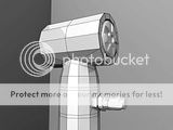
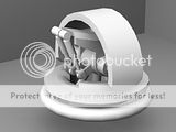
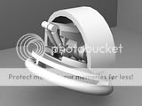
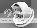
Okay here is the completed Proxy model for the basic ankle joint.

It is fully rigged. The top (entire ankle) rolls around the x-axis, the middle section with the pistons rolls around the z-axis (about +- 45 deg), and the bottom section rolls 360 deg around the y-axis.

I plan on completing the entire high res ankle assembly at a minimum. But I hope to complete the entire proxy and high res and completely rigged model in Maya.

Cheers

user added image
user added image
user added image
user added image
user added image


"If I have seen further it is by standing on the shoulders of giants." Sir Isaac Newton, 1675
# 11 21-11-2009 , 08:13 PM
ctbram's Avatar
Moderator
Join Date: Jan 2004
Location: Michigan, USA
Posts: 2,998
It's amazing what you can do in 24 hours without sleep!

I finished the foot so fast I decided to just keep going. I ended up "going" all night! Here is the almost COMPLETE proxy model of the full robot!

I still have to name every thing, setup the hierarchy, rig it and test everything out. I am sure I will need to adjust things. Rigging and testing will take a while and I may need to ask for help. I have piston rigging down but may run into other problems as I have just started dabbling with rigging. I like mechs as I don't have to deal with skin binding and painting influence weights. I will go with parenting and constraints for the whole model.

Please note this is just the PROXY model (no smoothing, nothing combined yet). I was very impressed with Andrew Browns video and so I decided to attack the whole model using the workflow he suggested in the video - build proxy, rig and test proxy, adjust design, then use proxy as a guide to creating the high-res version.

I hope to start on the HIGH-RES modeling in earnest in a few days.

Hammer - I promised it would get more complicated then then simple piston I was toying with. Is this more to your liking? (lol)

user added image


"If I have seen further it is by standing on the shoulders of giants." Sir Isaac Newton, 1675

Last edited by ctbram; 21-11-2009 at 09:17 PM.
# 12 21-11-2009 , 08:24 PM
daverave's Avatar
The thin red line
Join Date: Aug 2009
Location: England
Posts: 4,472
any close up wire frame shots please, god you did so much in 24 hours, i would have only got one of the guns done in that time.
looking good

# 13 21-11-2009 , 09:24 PM
ctbram's Avatar
Moderator
Join Date: Jan 2004
Location: Michigan, USA
Posts: 2,998
I am going to post shots of the build from the bottom up as I go through naming and putting the parts into their hierarchy.

I plan to do the same for the high-res build. I was gonna do some images of the process going from the proxy to the high-res parts.

If I can I was going to try to put together a couple camtasia videos showing some of the stuff I have recently figured out like rigging the three cylinder actuators used in the robot. I am also working on a short video to show how to use the mental ray contour option to make wire frame renders.

I learned alot from this video and although it was geared towards modo I find the basic workflow works well for Maya. I originally thought the tools in modo really put Maya to shame but after putting this model together I'd say the only features I wish maya had is the asset management system, some better axis alignment control (like action centers), the background constraint object, and a more reliable inset and thicken tool.

The main weakness I find in maya is axis alignment. They finally added options to align to edge and face for the move tool but scale and rotate axis are still wonky!

You have to create a helper object, align it, parent the part to it, and freeze transforms to get control of the scale and rotate axis. This really slows work flow.

I need to get some sleep though for now.


"If I have seen further it is by standing on the shoulders of giants." Sir Isaac Newton, 1675

Last edited by ctbram; 23-11-2009 at 03:06 PM.
Posting Rules Forum Rules
You may not post new threads | You may not post replies | You may not post attachments | You may not edit your posts | BB code is On | Smilies are On | [IMG] code is On | HTML code is Off

Similar Threads